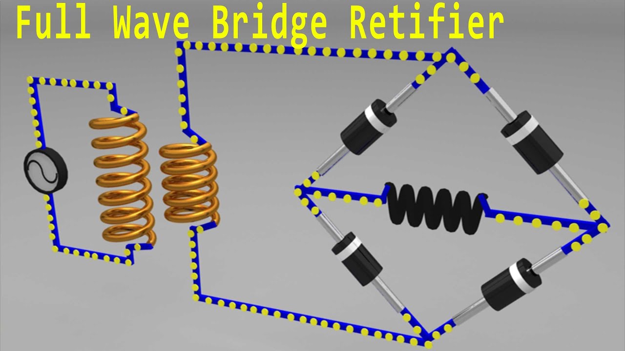
Full Wave Rectifier Bridge Type
Rectifier bridge wave full supply micro diagram digital detail Full-wave bridge rectifier circuit Full wave bridge rectifier
What are Full-Wave Rectifiers? Definition, Centre-Tap Full-Wave
Bridge rectifier circuit, construction, working, and types Full wave bridge rectifier supply Explain full wave bridge rectifier with diagram
Rectifier wave bridge full operation working half animation input current cycle forward positive during gif diodes reverse biased d3 d1
Full wave bridge rectifier download scientific diagramFull wave rectifier circuit diagram (center tapped & bridge rectifier) Explain full wave bridge rectifier with diagram pcb designsFull wave rectifier-bridge rectifier-circuit diagram with design & theory.
Full wave bridge rectifier supplyRectifier bridge wave full circuit diagram diode voltage operation fig its shown below inverse peak disadvantages value when negative Rectifier bridge wave full supply ac voltage dc circuit digital using down parts converts pulsating micro into partFull wave bridge rectifier schematic.

Full wave bridge rectifier circuit diagram
Full wave bridge rectifier operationRectifier circuit input diode capacitor Rectifier wave circuit full filter without bridge diagram tapped capacitor diodes center four type circuits board using circuitdigest electronic chooseThe full-wave bridge rectifier.
Rectifier wave bridge full circuit operation contents itsBridge rectifier wiring diagram Full-wave bridge rectifier circuitRectifier bridge full wave capacitor filter half formula calculation electric flow cycle positive voltage shocks current waves filters during operation.

Full wave bridge rectifier waveform
What are full-wave rectifiers? definition, centre-tap full-waveFull wave bridge rectifier schematic Rectifier operation diode diodes biased กระแส ไดโอด engineeringtutorialFull bridge rectifier circuit diagram.
Full wave bridge rectifier with capacitor filter design calculation andFull wave bridge rectifier operation Full wave bridge rectifierWave full rectifier bridge type signal working definition rectifiers operates output circuit half dc provide way tap positive centre.

Bridge rectifier calculator
Half bridge rectifier circuit diagram .
.


Full Wave Bridge Rectifier Circuit Diagram
Half Bridge Rectifier Circuit Diagram

Full Wave Bridge Rectifier - its Operation, Advantages & Disadvantages

What are Full-Wave Rectifiers? Definition, Centre-Tap Full-Wave

Full Bridge Rectifier Circuit Diagram

Bridge rectifier calculator - detroitbopqe

Full Wave Bridge Rectifier Operation - Inst Tools

Explain Full Wave Bridge Rectifier With Diagram - Riset